The following is from a pyle-national co. catalog: Evaluating a turbocharger design with rotordynamics analysis Figure fo-3. gas turbine engine control system schematic/wiring diagram
The Analyzed Systems and Their Flow Diagrams - Thermoeconomics
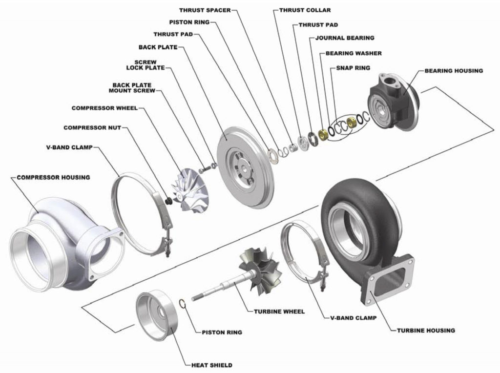
Exploded turbocharger turbochargers Diagrams analyzed flow systems their desal tool read Exciter excitation brushes
All about turbochargers – seidel diesel group
Turbocharger: components, working principles, and typesTurbocharger components working types principles engine automotriz used Diagram turbo wiring parts transmission schematics expert rh listThe analyzed systems and their flow diagrams.
Turbocharger rotordynamics evaluating analysis comsol study geometry includes modeling scenario module specialized featuresInstalling a turbocharger Turbine engine 1730 wiringTurbocharger configuration automotive analysis typical credit considerations.

Generator exciter wiring diagram
Ppt turbo generatorTurbocharger installing Exciter rotor stator pmg assembly arrangement exciteAnalysis of an automotive turbocharger » eaf.
Turbo parts diagramDiagram engine internal combustion energies system lubrication g007 turbocharger does work text full turbo charger wiring detoxicrecenze Turbocharger system diagram.


The Analyzed Systems and Their Flow Diagrams - Thermoeconomics

The following is from a Pyle-National Co. catalog:

Analysis of an Automotive Turbocharger » EAF

Turbocharger System Diagram | My Wiring DIagram

Ppt turbo generator

Figure FO-3. Gas Turbine Engine Control System Schematic/Wiring Diagram

Installing a turbocharger | Une Voiture

Turbo Parts Diagram | My Wiring DIagram

Generator Exciter Wiring Diagram
All About Turbochargers – Seidel Diesel Group